
-
High-frequency measurement system services Material testing Probe station Microwave anechoic chamber/shielded roomLan Cable Fully Automatic Tester Auto Switch fully automatic testing machine USB 4 / Type-C finished product line test system DisplayPort 2.1 finished product line test system HDMI 2.1 finished product line test system MCIO finished product line testing system Gen-Z finished product line testing system PCIE finished product line test system OCuLink Finished Product Line Test System QSFP/SFP finished product line test system HSD finished product line test system FAKRA finished product line testing system SAS/MiniSAS/SlimSAS Finished Product Line Testing System Raw Cable 20G/40G/50G Bare Wire Test System SATA/eSATA finished product line test system LVDS finished product line testing system Pre-test Integration ProjectElectromagnetic shielding test system Material electromagnetic parameter testing system Resistivity testing system Cable Shielding Effectiveness Test System Conductive gasket shielding effectiveness test system Reflection rate test system for absorbing materials NSS Noise Suppression/Absorption Sheet Performance Evaluation System Pre-compatibility testing systemUltra-low temperature vacuum probe station Automated probe station Manual probe station Displacement platform
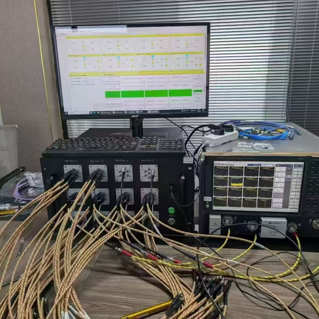


N5231A PNA-L Microwave Network Analyzer, 13.5 GHz
Category:
Network analyzer
Desktop network analyzer
Product Attachment:
- Product Description
- Selection
-
- Brand: 是德科技
- Commodity name: N5231A PNA-L Microwave Network Analyzer, 13.5 GHz
- Brand: Keysight Technologies
In-depth Analysis of the Keysight N5231A PNA-L Microwave Network Analyzer
I. Core Technical Parameters and Positioning
II. Typical Application Scenarios and Adaptability Analysis
- Passive Component Testing :
- S-parameter measurement of filters (such as 5G Sub-6GHz bandpass filters), couplers, and power dividers.
- Frequency response analysis of dielectric resonators (DROs), with accuracy up to 0.01Hz.
- Simple Active Component Evaluation :
- Gain flatness testing of low-noise amplifiers (LNAs), such as gain fluctuation < 0.5dB for 6GHz Wi-Fi modules.
- Conversion loss and port isolation testing of mixers, such as LO-IF isolation > 30dB.
- Material and Cable Characterization :
- Measurement of insertion loss (e.g., loss < 0.8dB/m at 13.5GHz) and voltage standing wave ratio (VSWR < 1.2) of RF cables.
- Extraction of complex permittivity of dielectric materials (such as FR4 substrates) using reflection/transmission methods.
- Cannot cover the millimeter-wave frequency band (such as above 24GHz). 76-81GHz automotive radar testing requires upgrading to the N5240A or higher model.
- For millimeter-wave expansion, an external down-conversion module can be used, but this will introduce additional loss (e.g., > 3dB at 20GHz).
III. Key Considerations for High-Frequency Testing
- Standard N-type (50Ω) interface. High-frequency testing requires the use of low-loss, phase-stable cables (such as the Keysight 85133D series) to avoid the loss of ordinary N-type cables above 10GHz (ordinary N-type cables have a loss > 0.6dB/m at 13.5GHz).
- Calibration Fixture Selection:
- Below 13.5GHz: Use the 125A series N-type precision calibration kit (covering 10MHz-18GHz).
- If an external module is used to expand to 20GHz: A 3.5mm precision calibration kit (such as 125B-265) is required.
- Electronic calibration (ECal) is implemented via the 85032E module for fast calibration (<30 seconds), reducing manual calibration errors (such as directivity error < 0.05dB).
- Testing is recommended at 23±2℃ to avoid temperature drift causing measurement fluctuations (a 1℃ drift causes a 0.01dB amplitude error).
- For higher frequency or extended functionality, consider upgrading to the N5231B (13.5GHz, supports touchscreen and automated testing) or N5222A (9kHz-20GHz, supports vector signal analysis).
IV. Discontinuation and Support Status
- The N5231A entered the "limited support" phase in June 2024, and repair and calibration services are gradually being reduced.
- Keysight Technologies hardware/firmware upgrade program is recommended for migration to the B model, at a cost of only 30-50% of a new product.
- Fully compatible with the N5230C; existing test codes and fixtures can be reused directly, protecting users' existing investments.
V. Summary: Selection Decision Reference
- Recommended Scenarios :
- University laboratories or small and medium-sized enterprise R&D with limited budgets but requiring coverage of frequencies below 13.5GHz.
- Mass production testing of Sub-6GHz RF components (such as filters and antennas).
- Preliminary evaluation of simple active devices (such as LNAs and mixers).
- Pitfalls to Avoid :
- Avoid use for testing above 13.5GHz (such as 5G millimeter wave).
- High-frequency testing requires low-loss cables and high-precision calibration components to ensure system error < 0.1dB.
-
I. Hardware Characteristics and Option Configurations
1. Basic Parameters and Performance
- Frequency Coverage : 300 kHz to 13.5 GHz, suitable for testing wideband components such as filters, antennas, and amplifiers.
- Dynamic Range : At 20 GHz, it reaches 133 dB with trace noise as low as 0.004 dB rms (1 kHz IFBW), supporting high-precision, low-loss measurements.
- Output Power : Extended power range to -55 to +13 dBm with a built-in 60 dB step attenuator, meeting the needs of amplifier linearity/nonlinearity characteristic analysis.
- Scan Speed : 6 ms/201 points supporting fast batch testing.
2. Calibration and Accessories
- Mechanical Calibration Kit
- 85052D : 3.5 mm calibration kit, covering 300 kHz to 20 GHz, supporting SOLT calibration.
- 85052D-001 : 2.4 mm calibration kit, suitable for high-frequency testing (such as 40/50 GHz expansion).
- Electronic Calibration (ECal) Module
- N4691A : Single-connection fast calibration, supporting 2 ports, reducing human operational errors.
- Test Cable
- 85131F : 3.5 mm flexible test cable, suitable for the 300 kHz to 20 GHz band, ensuring signal integrity.
3. Function Expansion Options
- -010 Time Domain Measurement : Supports pulse signal analysis (such as radar module dynamic response), with pulse width as low as 2 μs.
- -080 Frequency Offset Measurement : Analyzes the frequency conversion loss and distortion characteristics of mixers/amplifiers.
- -416 4-Port Configuration : Integrates a configurable test device, supporting S-parameter measurement of multi-port networks.
- -1CP Rack Mounting Kit : Adaptable to standard 19-inch cabinets, improving production line integration.
- -UK6 Calibration Certificate : Provides an official calibration report with test data, meeting quality certification requirements.
II. Software Functions and Application Scenarios
1. Advanced Measurement Functions
- Fixture De-embedding : Through TRL/LRM Calibration eliminates the influence of the test fixture, suitable for high-precision measurement of wafer-level and packaged devices.
- Mixer/Converter Testing : Built-in wizard automatically measures frequency conversion loss, local oscillator (LO) leakage, and other parameters, simplifying radio frequency front-end design verification.
- Multi-Mode Scanning : Supports linear/logarithmic/power scanning, adapting to the testing needs of different devices such as filters, antennas, and amplifiers.
2. Automation and Compatibility
- Built-in VBA Programming : Customizes test scripts, batch executes multi-port S-parameter scanning, data storage, and report generation.
- Spectrum Analysis Function : Through the option -090 integrates a spectrum analyzer, realizing joint analysis of signal integrity and frequency domain characteristics.
3. Typical Applications
- Wireless Communication
- Tests the in-band loss and out-of-band suppression characteristics of 5G intermediate frequency filters.
- Evaluates the S-parameters and signal integrity of Wi-Fi 6E antennas.
- Materials and Semiconductors
- Analyzes the dielectric constant and loss characteristics of high-frequency substrates (such as FR4, PTFE), supporting TRL calibration.
- Combines with a wafer probe station to perform S-parameter testing of on-chip components (such as radio frequency transistors).
- Education and Research
- Basic radio frequency teaching experiments (such as Smith chart analysis, impedance matching).
- Low-cost solution development, suitable for budget-sensitive laboratory environments.
III. Discontinued Status and Replacement Suggestions
- N5231B Supports an intuitive graphical interface and a fast calibration process, suitable for scenarios requiring high integration and ease of operation.
- N5232B Expands the frequency to 20 GHz, compatible with existing test fixtures and scripts, suitable for high-frequency component development.
IV. Configuration Suggestions
- Basic RF Testing Optional -010 (Time domain measurement) + 85052D Calibration kit + N4691A ECal module.
- Material Analysis Optional -010 + 85052D-001 High-frequency calibration kit + dielectric test fixture (e.g., Keysight 16453A).
- Automated Production Line Optional -1CP (Rack mount) + -416 (4-port configuration) + Customized VBA script.
Previous Page
Previous Page
Product Consultation
Please fill out the form below, leave your contact information and needs, and we will be happy to serve you!
Contact Information
Add.: 2nd Floor, Building C, Zhongzhi Zhichuang Park, Yucui Community, Longhua Street, Longhua District, Shenzhen City, Guangdong Province, China
Tel: +86-135 1042 6680
Email: harriosn@sengt.com
Follow us

Follow us